The Single 12V Rail SilverStone Olympia OP650
by Christoph Katzer on July 13, 2007 12:00 PM EST- Posted in
- Cases/Cooling/PSUs
Secondary Side
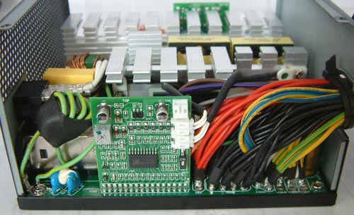
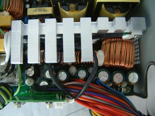
The secondary side has its own printed circuit board just as the primary side does. The board contains the protection features (including OCP, OPP, SCP, and UVP) and the fan control. The fan control is connected to two temperature sensing diodes which have been attached to the secondary heatsink (the hotter heatsink while running). They are attached on the right and left side and interact with each other to control the speed of the fan. The upper connector on the PCB is the output to the fan on the upper side of the power supply. The output is controlled through a potentiometer.
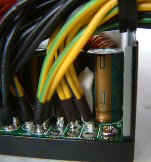
On the lower right edge of the PCB we found a small switch. This switch is actually to turn off the OCP on each of the four 12v rails to "combine" them into a single one. This is a very common method as most other manufacturers approach rail separation the exact same way. Normally separated 12v rails can be generated with just these separated OCPs on each rail. They have one or two 12v rails and just split them into a few more in order to show a higher number of 12v rails.
All the capacitors on the secondary side are from Taepo. The company is quite popular and used by many other manufacturers as well. The cables are nicely connected to the PCB and all of the cables have shrinking hoses in the end, how it should to be for certain security matters. The coils have a very good winding quality like all the others in this PSU as well. It would have been nice if Silverstone had started the sleeves of the cables inside of the PSU. This raises the overall quality and importantly for most users it looks better.
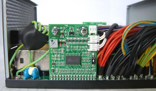
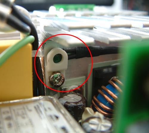
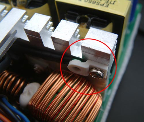
The secondary side has its own printed circuit board just as the primary side does. The board contains the protection features (including OCP, OPP, SCP, and UVP) and the fan control. The fan control is connected to two temperature sensing diodes which have been attached to the secondary heatsink (the hotter heatsink while running). They are attached on the right and left side and interact with each other to control the speed of the fan. The upper connector on the PCB is the output to the fan on the upper side of the power supply. The output is controlled through a potentiometer.
On the lower right edge of the PCB we found a small switch. This switch is actually to turn off the OCP on each of the four 12v rails to "combine" them into a single one. This is a very common method as most other manufacturers approach rail separation the exact same way. Normally separated 12v rails can be generated with just these separated OCPs on each rail. They have one or two 12v rails and just split them into a few more in order to show a higher number of 12v rails.
All the capacitors on the secondary side are from Taepo. The company is quite popular and used by many other manufacturers as well. The cables are nicely connected to the PCB and all of the cables have shrinking hoses in the end, how it should to be for certain security matters. The coils have a very good winding quality like all the others in this PSU as well. It would have been nice if Silverstone had started the sleeves of the cables inside of the PSU. This raises the overall quality and importantly for most users it looks better.


46 Comments
View All Comments
YellowWing - Friday, July 13, 2007 - link
In a prior article you showed us the box you use for testing power supplies. I don't remember reading how the heat generated by the power supplies is removed from the sealed box. Does the temp of the air in the box rise with time? Would the drop off in voltage be less with full ventilation?YellowWing - Friday, July 13, 2007 - link
Brownouts have caused power supply failures for me in the past. How about dialing the input voltage down to 90 or so and see what happens.From experience I can say that some supplies don't survive at lower input voltages.
DerekWilson - Friday, July 13, 2007 - link
we are considering looking at 90V input. Thanks for the suggestion.bpt8056 - Friday, July 13, 2007 - link
I just want to say that I thought AT did a great job on the review. Keep up the great work!puffpio - Friday, July 13, 2007 - link
Great article..looking forward to many many moreOn one of the graphs of the 230V tests, it is labeled as 115V
jonnyGURU - Friday, July 13, 2007 - link
Good job. Clearly a lot of effort was put behind putting the methodology and this review together.Couple questions..
1. How much of the voltage drop shown would you contribute to the resistance created by the interface board and wires located between the end of the PSU's connector and the actual load. This isn't my favorite power supply, but I know the voltage regulation isn't nearly as bad as you have it graphed. And naturallly, since load also creates resistance, your voltage is going to decrease exponentially if you're not loading and measuring at the end of the connector. Since you're using a Chroma, I know you're not loading and measuring at the connector. Perhaps you could rig a DMM to measure voltages at the end of the connector instead of reporting what the Chroma is telling you since the Chroma is going to be incorrect since it doesn't take into consideration this added resistance.
2. Do you think it's possible to define "10%, 20%, etc." as it pertains to your loads. Naturally, you can't load all rails by 80%, 90%, 100%" because you'd easily exceed the power supplies capabilities. And certainly you're not loading the +12V with 80%, 90% 100% and then filling up the remainder with a 3.3V and 5V load because then you would crossload the PSU with an unusually high +12V load.
3. And, at risk of sounding like I'm beating a dead horse, ripple and noise results. We all know spec is 1%, and ripple and noise does typically increase with load. It would be nice to see if the power supplies being tested stay within that spec. through out it's total advertised capability.
Thanks and I look forward to the next PSU review!
mcvan - Saturday, July 14, 2007 - link
Like Johnny said. ;)Another issue pertinent to the extreme sag in voltage lines and perhaps to the soaring temperatures is to ask how long the PSU was run at each load level (and in total) and what was the air temperature at the PSU intake? Maybe the test box is just letting the PSU get way too unnaturally hot, and this has a deleterious effect on performance. This test box is not the same as thermal control chamber where you can dial in a specific target temperature, which will then be held constant by the chamber throughout the testing.
Since the test box is well insulated and sealed, there is a direct correlation between time spent with the PSU on and internal air temperature. No matter how the PSU is cooled, at any load, the temperature of the test box should rise continuously (even if only incrementally at very low load) as long as the PSU is running. This is a significant uncontrolled and unreported factor. That PSU intake temperature will be dictated by a complex mix of factors, by too many variables --
-starting ambient air temp in the box
-how long the PSU is kept running in the box and at which loads
-heat loss out of the box
-efficiency curve of the PSU
-fan and fan controller characteristics
If the time spent at each load and the starting ambient temp is kept the same for each and all PSUs, then the variables are correctly contained to the PSUs being tested. Then differences in the air temperature at the intake at any given power level for each PSU would reflect real differences in the cooling system and efficiency of each PSU. It would ensure a more level thermal playing field.
qpwoei - Friday, July 13, 2007 - link
While we're beating dead horses, I'll land a few blows on the dynamic load response horse as well :)
SilthDraeth - Friday, July 13, 2007 - link
Seems like you know what you are talking about. I hope they take some of your points into consideration, since they all seem very valid.jonnyGURU - Friday, July 13, 2007 - link
Thanks. But I'm just an old hack. ;)