The Single 12V Rail SilverStone Olympia OP650
by Christoph Katzer on July 13, 2007 12:00 PM EST- Posted in
- Cases/Cooling/PSUs
Secondary Side
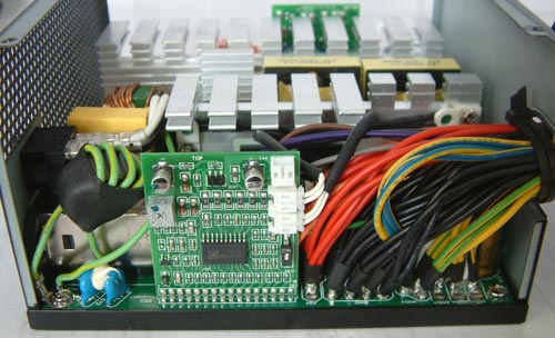
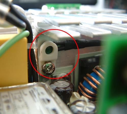
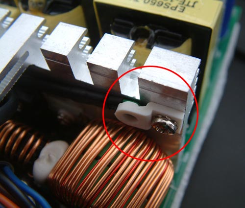
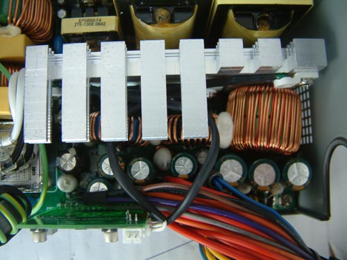
The secondary side has its own printed circuit board just as the primary side does. The board contains the protection features (including OCP, OPP, SCP, and UVP) and the fan control. The fan control is connected to two temperature sensing diodes which have been attached to the secondary heatsink (the hotter heatsink while running). They are attached on the right and left side and interact with each other to control the speed of the fan. The upper connector on the PCB is the output to the fan on the upper side of the power supply. The output is controlled through a potentiometer.
On the lower right edge of the PCB we found a small switch. This switch is actually to turn off the OCP on each of the four 12v rails to "combine" them into a single one. This is a very common method as most other manufacturers approach rail separation the exact same way. Normally separated 12v rails can be generated with just these separated OCPs on each rail. They have one or two 12v rails and just split them into a few more in order to show a higher number of 12v rails.
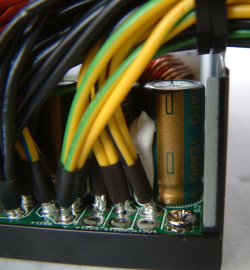
All the capacitors on the secondary side are from Taepo. The company is quite popular and used by many other manufacturers as well. The cables are nicely connected to the PCB and all of the cables have shrinking hoses in the end, how it should to be for certain security matters. The coils have a very good winding quality like all the others in this PSU as well. It would have been nice if Silverstone had started the sleeves of the cables inside of the PSU. This raises the overall quality and importantly for most users it looks better.
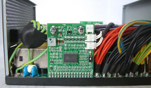
The secondary side has its own printed circuit board just as the primary side does. The board contains the protection features (including OCP, OPP, SCP, and UVP) and the fan control. The fan control is connected to two temperature sensing diodes which have been attached to the secondary heatsink (the hotter heatsink while running). They are attached on the right and left side and interact with each other to control the speed of the fan. The upper connector on the PCB is the output to the fan on the upper side of the power supply. The output is controlled through a potentiometer.
On the lower right edge of the PCB we found a small switch. This switch is actually to turn off the OCP on each of the four 12v rails to "combine" them into a single one. This is a very common method as most other manufacturers approach rail separation the exact same way. Normally separated 12v rails can be generated with just these separated OCPs on each rail. They have one or two 12v rails and just split them into a few more in order to show a higher number of 12v rails.
All the capacitors on the secondary side are from Taepo. The company is quite popular and used by many other manufacturers as well. The cables are nicely connected to the PCB and all of the cables have shrinking hoses in the end, how it should to be for certain security matters. The coils have a very good winding quality like all the others in this PSU as well. It would have been nice if Silverstone had started the sleeves of the cables inside of the PSU. This raises the overall quality and importantly for most users it looks better.


46 Comments
View All Comments
Martimus - Friday, July 13, 2007 - link
It was a nice article. I know not to buy this PSU now when I build my roommates computer later this month. I don't like how it falls out of spec at high loads. I would like to see a review on the PC P&C 750W Silencer Quad, as that was what I was planning on using for his computer.Looking at that board frightened me, seeing as how much power was in that supply, and how close together the components were. I hope that they can increase the size of the standard power supply to help alleviate this problem now that we are building computers that have such high loads. I used to design and test power supplies (albeit for automotive conponents) and seeing how they crammed those parts so close together was scary. That is an easy way to kill the reliability and life of your supply. The heat just kills the board and components. Although it does reduce problems like parasitic capacitance. Maybe that is why many manufactures are avoiding using the top mounted 120mm fan; to keep from having to package the component like that.
yacoub - Friday, July 13, 2007 - link
But doesn't that mean the motherboard will need to use its little battery backup to keep the BIOS settings? Turning off the PSU switch and/or unplugging the cable to fully remove power sounds like a way to kill your motherboard's battery quickly.
mindless1 - Wednesday, July 18, 2007 - link
It is only a "suggestion", there is just as valid an argument to not unplug it unless you're on a quest to save every last bit of power possible which is a nobile goal but put in perspective, a bit of a band-aid since anyone using a modern computer to access webpages is wasting orders of magnitude more power, even ignoring the typical products with large power consumption.It might be said that unplugging also provides some protection against surges, limiting exposure to them, but it's really something that would have to be considered on a per-site basis, remembering that most people don't unplug their computers any day of the year and seldom is surge damage a recurring problem. IOW, a matter of how much extra effort to put forth to guard against something that, statistically, isn't likely to happen.
DerekWilson - Friday, July 13, 2007 - link
iirc, your mobo battery is in use when the computer is off and the PSU is on anyway. i could be wrong ... its been like a decade since i paid attention to that.But either way, mobo batteries last years even when their not powered up.
SpaceRanger - Friday, July 13, 2007 - link
Very nice work on AT's first PSU review with such detail. One question though, what happened to the Ripple and Noise results from the PSU? In the methodology they were mentioned to be tested, yet not in this review?Looking forward to more PSU reviews..
Shadowmage - Friday, July 13, 2007 - link
I agree. The reviews must have ripple. That's why Jonnyguru's reviews are so highly regarded.mindless1 - Wednesday, July 18, 2007 - link
and yet, we don't really need to know the ripple values so long as they stay within ATX specs at the max rated loads and all crossloading combinations possible. Within these limits, lower ripple is not necessarily "better" per se, if it were important to have lowest possible ripple we wouldn't be using switching PSU at all or they'd at least have an addt'l stage of LC filtration before the output.LTG - Friday, July 13, 2007 - link
The first page leaves out an explanation of why multiple rails are used in the first place.I'm sure many technical software people, who don't know hardware, wonder like I do, why wasn't it always just one rail?
Just a couple sentences would probably be helpful.
thanks.
qpwoei - Friday, July 13, 2007 - link
A PSU having multiple rails just means that a single rail in the PSU runs through a number of parallel current limiters - so all lines on the 12V1 rail go through one 20A current limiter, all lines on 12V2 go through another, etc. This is done as IEC safety requirements (and consequently ATX PSU requirements) say that "operator accessible" connections must not be able to deliver more than 240 VA (ie: 20 A at 12 V).In older PSUs, only a single current limiter was used as there was no requirement for maximum current per line. In many recent PSUs, the single current maximum is starting to come back as well due to the high current requirements of modern GPUs and motherboards.
mindless1 - Wednesday, July 18, 2007 - link
While it is common (because it's cheaper to implement) for a 12V multi-rail PSU to use parallel current limiters, it is not necessarily true that all are designed this way, typically only those built towards lower component cost instead of higher sustainable current. Other options include having separate capacitance after the current limiter (resistor), or a second inductor-cap LC stage, or additionally a separate rectifier stage, or additionally a separate transformer (essentially going backwards towards building in a 2nd supply until available space and budget limit it).