ASRock Z77 Extreme6 Review: Legacy Bites Back
by Ian Cutress on July 13, 2012 2:00 PM EST- Posted in
- Motherboards
- ASRock
- Z77
ASRock Z77 Extreme6 BIOS
The BIOS is the central nervous system of the computer - it decides where signals between all the different components should go (in this analogy, the CPU is the muscles, the RAM is the brain, the GPU is the visual cortex, I have no idea what the liver or gall bladder would be...). It is a very important part of the whole package, so the BIOS must be coded properly and loved by the manufacturer. It should be simple enough to make it easy for users but also offer the level of complexity that enthusiasts would want.
We briefly tackled ASRock's BIOS when we looked at the Z77 Extreme4 - in comparison, there are a few nuances with the Z77 Extreme6 that I should mention here. My normal BIOS policy when getting a board in for review comes in two forms. If I received the motherboard before release, when it comes around to reviewing I will update to the latest publicly available BIOS at the time; if I receive the board after the chipset has some footing in the market, I will review it as-it-comes.
My sample from ASRock was on a very early 1.01 beta BIOS, so I upgraded it to 1.70. This version comes with some extra features (Internet Flash, Dehumidifier) which I will mention later. The original BIOS, should you have it, it worth updating - the early revisions were slightly unstable and would hang from time to time.
Neither BIOS was entirely happy with my memory choice - my kit for Ivy Bridge reviews is a G.Skill 16GB DDR3-2400 9-11-11 kit (F3-19200CL9Q-16GBZMD), which works in most Z77 motherboards without an issue. With a few motherboards, I have to raise VTT from automatic to 1.3 volts. I had to do that with the Z77 Extreme6, but even then the system would fail to boot or BSOD every now and again. All the testing was complete at XMP for this kit, albeit in batches when it was working.
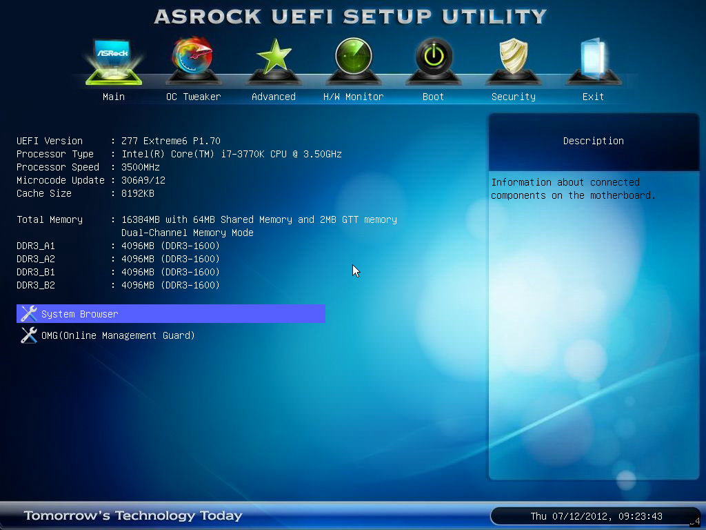
The BIOS itself in terms of features is a packed as the Z77 Extreme4. Our front screen gives us a lot of information that we like to see from a BIOS - the motherboard being used and the BIOS version; the CPU and CPU speed; the total memory on board, as well as a break down per memory stick and current speed of those modules. All we are really missing is some form of persistent temperature value present on the screen, and perhaps some voltage readings.
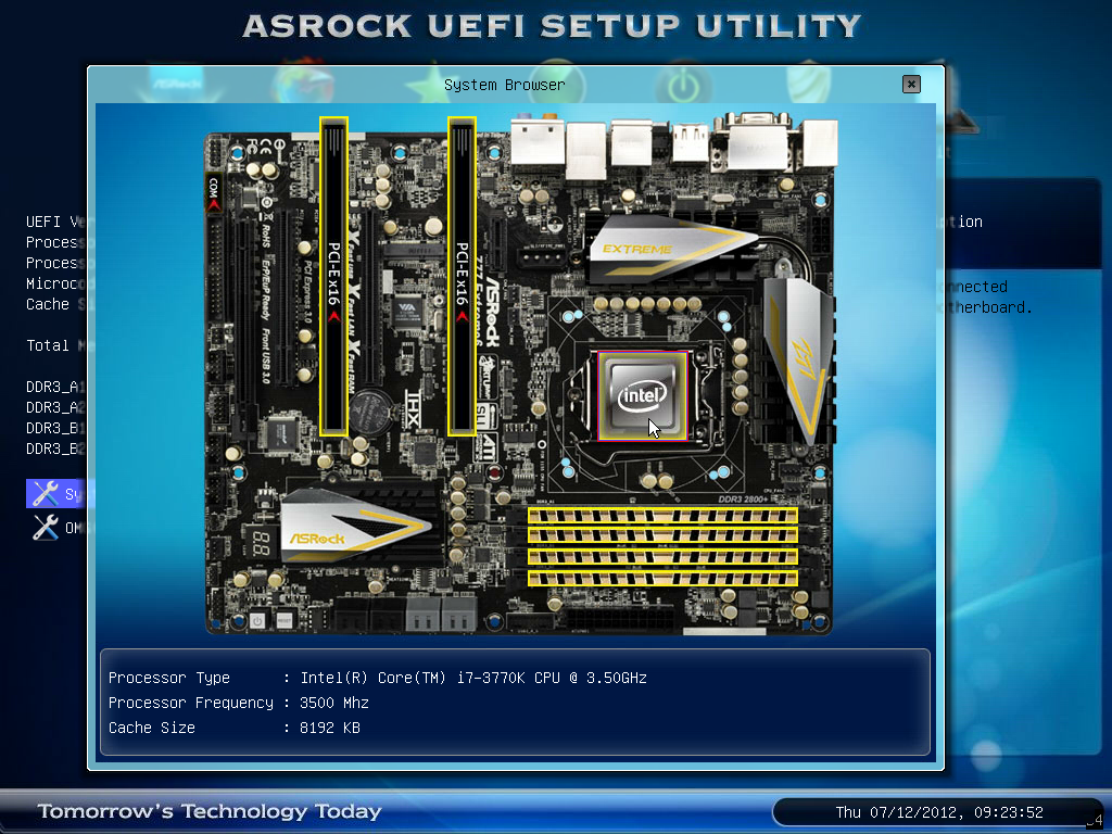
On this front screen are two additional features that do not really fit into the rest of the BIOS. The first is the system browser, which is a top down image of the board installed with all the components inside it identifiable. This is handy if some hardware is not being seen - if it is not here in the system browser then chances are the operating system will not initialize it (i.e. a memory stick or 2nd GPU dies).
The other feature on the main screen is the Online Management Guard, or 'OMG'. The premise of this comes down to disabling the internet features of a motherboard for certain times of the day to restrict access for younger users. There are several easy ways for those users to disable it however - either by changing the system clock, or by going into the BIOS and changing it manually. There is also the possibility that using a WiFi dongle would get around this, as the BIOS can only control the network port on the motherboard.
The main section of the BIOS is in the OC Tweaker menu, which deals with overclocking. For automatic overclocks, we have the Advanced Turbo 30 option that gives a 4.7 GHz overclock on the system, and CPU OC/GPU OC settings that give predefined values for each value to reach desired overclocks. These will be tested in the next page of the review.
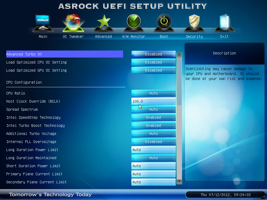
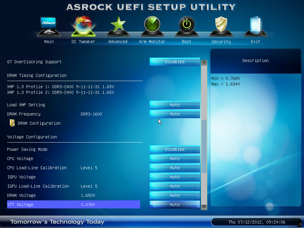
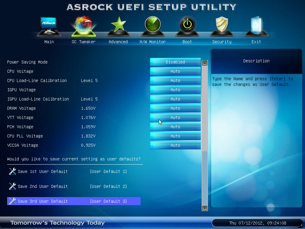
The rest of the OC Tweaker menu is standard. CPU Ratio can be selected per core or for all cores, and BCLK can be adjusted appropriately. Adjusting the BCLK also directly affects the value chosen for the memory strap, which is always good to see. Power limits and turbo boost options are also here. Memory settings are found under the CPU settings, and voltage settings are underneath that. Thankfully, ASRock are nice and thorough on describing each of the features, especially the Load Line Calibration - sometimes it is never clear if LLC Level 1 or Level 5/10 is the optimal setting for constant voltage, but ASRock provide a handy diagram for users. Three profiles can also be saved.
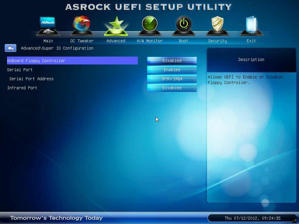
By default, ACHI is enabled (a good setting), and the onboard Floppy port is disabled. Users can enable the Floppy port by going to Advanced -> Super IO Configuration as shown below.
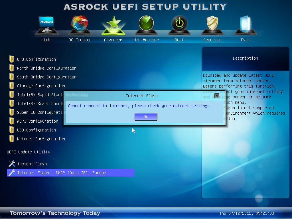
In order to update the BIOS, ASRock have an option to flash from a USB stick whilst in the BIOS (nothing new there), but also a novel feature called Internet Flash. Part of their BIOS code contains networking protocols such that users who have a non-login wired internet connection can directly probe ASRock's servers and download the latest BIOS. My testbed setup uses an esoteric combination of WiFi and ICS, and thus this was not applicable in my usage scenario. However, it is a great feature to have in a BIOS, and I fully expect other motherboard manufacturers to copy this.
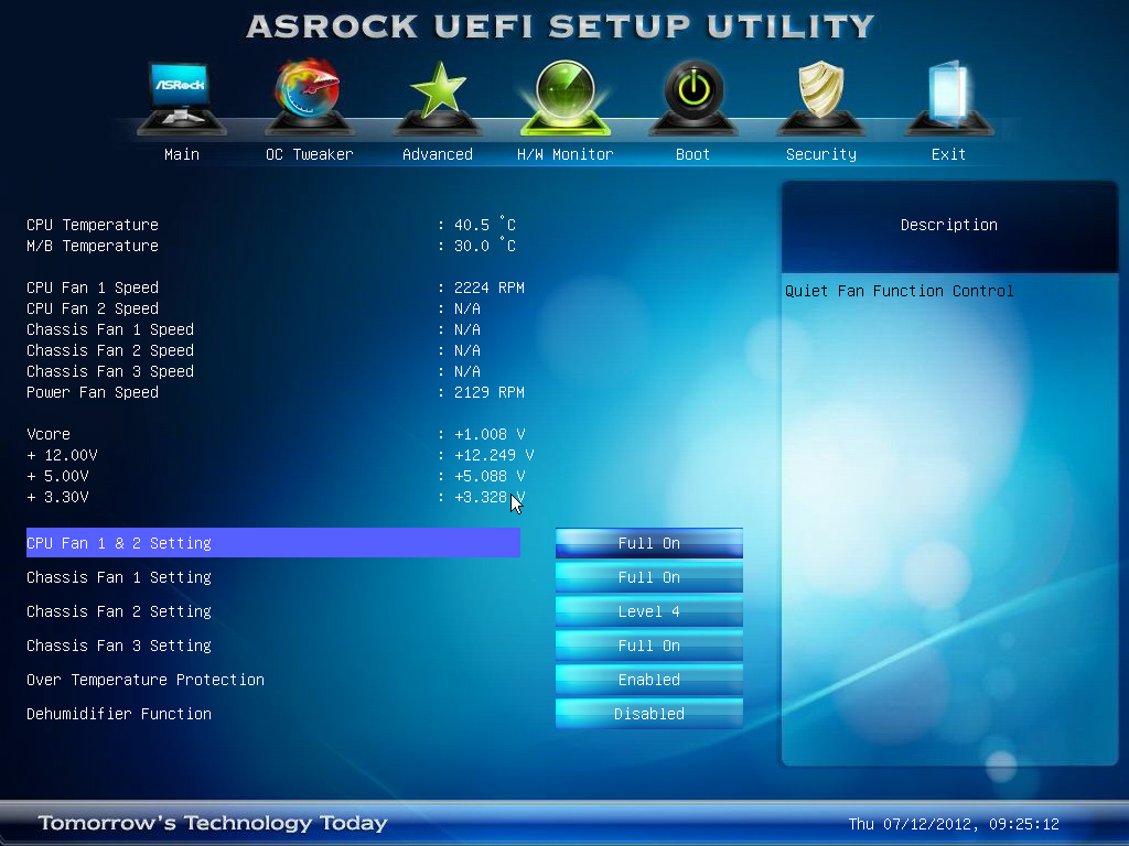
Fan controls from ASRock have been in the past a little confusing and disappointing in the past. While some of ASRock's competition allow users to specify a gradient between minimum and maximum RPM of a fan on a header, ASRock relies on using 'Target Temperatures' and 'Target Speeds', which use various levels to describe the ferocity of the fan. This is not an ideal situation if it requires users to try to understand how it works. The interface should be clean and easily selectable.
ASRock's last surprise comes in the form of their 'Dehumidifier' function. This is a very odd feature, especially as it is inappropriately named for the western hemisphere, where dehumidification has only one specific meaning of actually taking water out of the air. Let me take you through the ASRock usage scenario:
You have a PC in a very humid climate, where humidity is in the high 90%. When you use the PC for gaming, the temperature inside the case rises. As air gets warmer, it can hold more water.
Therefore, if we have (for example) 4 grams of water in a case at 40ºC, the specific humidity of that air is greater than a situation where we have 4g of water in a case at 60ºC. But at 60ºC, the air can hold more water (say 6g). When the PC is turned off, or the localized air gets cooler, the air inside the case can get cooler, and when the air reaches 100% specific humidity, the water vapor leaves the air and condenses on components. ASRock's Dehumidifier function makes the PC spin up the fans for a periods of time during the day to remove the hot air that has accumulated during the day from the case, and replace it with cooler air, but at the same time the hot air takes away the extra water vapor with it.
It can get confusing as well if you consider where the extra water vapor would come from. Scientifically, it deals with the balancing of specific humidity across two adjacent temperature zones. Using arbitrary numbers, consider two pockets of air close to each other. Each holding 2g of water vapor (so 4g total), but the first pocket of air (A) is at 40ºC, with a specific humidity of 100%. The second pocket of air (B) is at 80ºC, with a specific humidity of 50%. The water vapor will migrate from A to B, in order to balance the specific humidity. This would mean that in the end, A would still be 40ºC (assuming no heat transfer), but hold 1g of water with a specific humidity of 75%, and B would still be 80ºC, but hold 3g of water with a specific humidity of 75%.
If suddenly the temperature of B dropped to 40ºC, then 1g of water would condense out of the air, leaving it with 2g of water (specific humidity of 100%). This is the scenario ASRock are hoping to avoid with the 'Dehumidifier' function. Perhaps 'Dehumidifier' is the wrong thing to call it, but it is there if this is your scenario.
(For completeness, A and B would again equilibrate to 87.5% relative humidity (1.5g of water each) at 40ºC. There is then the possibility that they would reabsorb some of the condensed water back until none was left. Please note I was using arbitrary numbers to showcase a point, rather than exact calculated values for a given volume)


Software
ASRock love to include licensed software in their motherboard bundles. Their main marketing feature is the '555 XFast' motif, covering XFast LAN (licensed software), XFast USB (licensed software), and XFast RAM. Each of these will be covered in turn. But first, let us start with the ASRock eXtreme Tuning Utility, or AXTU.
ASRock eXtreme Tuning Utility
AXTU has been part of the ASRock bundle for a while now. It attempts to emulate to a certain extent ASUS' AI Suite, in the sense that it should have all the motherboard features in one interface. ASUS' design has been refined over the years, while ASRock's remains simple:
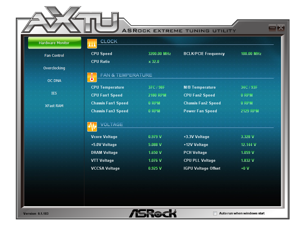
Options include the hardware monitor, fan controls, overclocking, OC DNA (for sharing BIOSes), IES (Intelligent Energy Saver), and XFast RAM. The hardware monitor is as you see above - we have access to a lot of data for the CPU, voltages, temperatures, and fan speeds. A lot of this would be a good inclusion on the first BIOS page (hint hint).
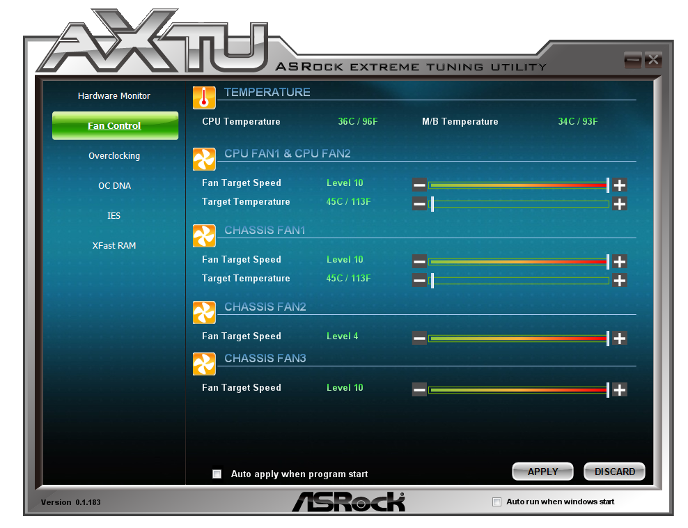
The fan control settings are easier to manipulate than those in the BIOS, however there is scope to improve the visual aspects of this interface with graphs and so on.
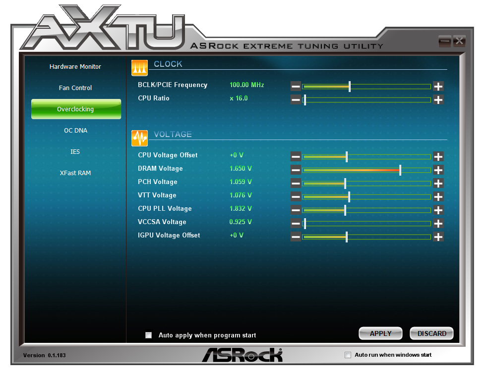
Overclocking options on the other hand are a little tame, giving no direct control for inputting values - everything is done on the sliders. The voltages are a little confusing, as it shows neither the current values set by the BIOS nor the current values as per the CPU load. Giving users only an offset voltage to play with is a little frustrating.
The Intelligent Energy Saver function attempts to reduce the voltage on the CPU as well as the number of power phases in use at any one time.
XFast RAM is a feature ASRock are using to help speed up certain features of the motherboard. ASRock recognize that users of Z77 motherboards can pick up memory very cheaply, so it would be common enough to see 16 GB of memory in a system. Even as an enthusiast, I have only ever seen my 16 GB system hit 8 GB a single time and that whilst playing a game and having 100s of internet tabs open at once. Thus ASRock have said that it would be worthwhile donating part of that memory into a RAMDisk, which acts as a fast store for temporary files.
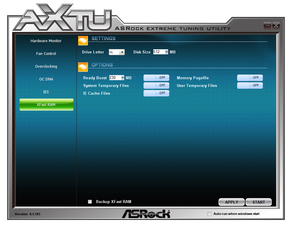
Users can thus partition off part of their memory to deal with temporary cache files as required. Reading from the memory is a couple of orders of magnitude quicker than the solid state drive, in terms of both latency and throughput, which means the system should be sped up quite effectively when loading temporary files.
XFast LAN
Licensed from cFosSpeed (in much the same way that ASUS' ROG GameFirst software is), ASRock have included a software driven networking utility as part of their software bundle.
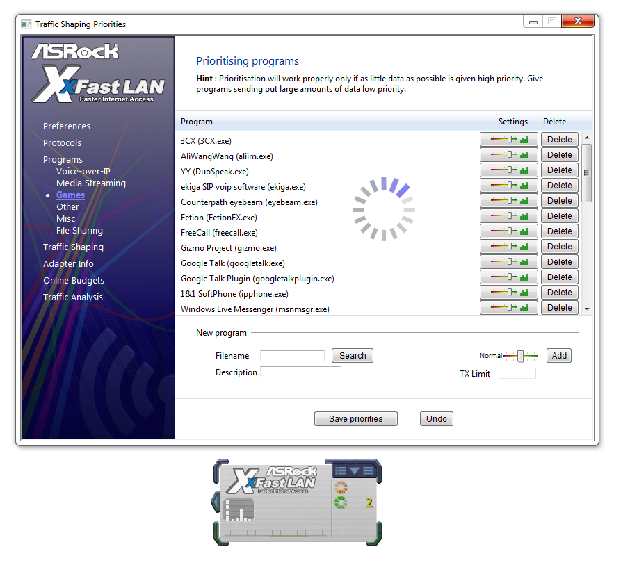
This utility allows users to decide what has priority over the networking protocol. Should a gamer ever decide that he or she needs to heavily download while playing online games, this can be managed here. On the other hand, perhaps VoIP needs priority, or media streaming tools. XFast LAN also allows for port management of the network, as well as traffic analysis and monitoring.
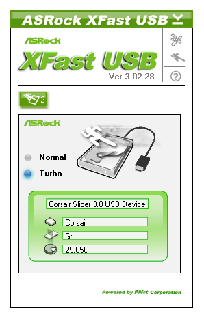
XFast USB
One feature that is crying out for Windows 8 is the overhaul of USB protocols. When Windows 7 had first come out, USB 3.0 was still in its infancy, and the standard set of USB commands were available. This is still true today with Intel's standard chipset drivers. One way of increasing USB throughput is to disregard latency, using Bulk Only Transfers (BOT). This is what XFast USB does - it overrides the USB driver in order to use its own commands. The stage above BOT is UASP, which will feature by default in Windows 8 with appropriate hardware. But for now, ASRock are giving XFast USB on a port-by-port basis, working on both USB 2.0 and USB 3.0 for a single device at a time. In our testing, it definitely speeds up the peak transfer rate, saving 20% time on our USB transfer test.


35 Comments
View All Comments
nubie - Saturday, July 14, 2012 - link
Yes, a COM port and Serial port are generally the same thing.I much prefer Parallel, because I am "bit-banging" to program an Atmega micro-controller, a I2C EEPROM, or an SPI EEPROM.
Although I do have a couple Packard Bell Fast Media Infrared (FMIR) receivers that demand a COM port, as does the (sadly lacking drivers newer than Win98) 6-axis Spacetec Orb controller.
Meaker10 - Saturday, July 14, 2012 - link
Without looking at the specs the mini slot is pci-e (for wifi) as it is half height and msata slots need to be full height.repoman27 - Saturday, July 14, 2012 - link
I thought one of the features of the Z77 chipset was that you could select between 1 x16, 2 x8, or 1 x8 + 2 x4 for the PCIe 3.0 lanes coming off of the CPU? In which case you wouldn't need an additional PCIe switch and all three cards would get at least 32 Gbps of PCIe bandwidth...Also, Ian, you seem to have some persistent dyslexia going on when it comes to the model names of PLX's PCIe switches; it's "PEX 8747", not "PXE 8747". There are other options available as well, such as the smaller, cheaper PEX 8724, which would have allowed them to offer effectively 3 x8 PCIe 3.0 slots.
scott967a - Saturday, July 14, 2012 - link
Do you guys ever test wake on lan or other wake up functions? Reason being for the first time I thought I would set up an old sys using Abit P35 Pro for WoL with fail result. Not sure if it is operator error or MB/BIOS problem but searching online doesn't yield much info on WoL performance.529th - Sunday, July 15, 2012 - link
Thank you for including a DPC latency test. Thank you Thank you Thank you! ha...Which app are you using to check DPC latency, btw?
Please include DCP latency testings in your future Motherboard testings as well. I will be jumping on the Haswell wagon when it comes through town.
Cheers
529th - Sunday, July 15, 2012 - link
And also include the BIOS that it's being tested on. Thanks :)IanCutress - Sunday, July 15, 2012 - link
As you can perhaps tell from our DPC Graph, we've been testing it quite a while. And in the explanation of said test, I do mention the program I use - DPC Latency Checker. Quick Google will find it. Currently I'm rarely finding a motherboard on a mainstream chipset that severely fails it - usually it is the included monitoring software that causes peaks of 2000+. If this happens, disable your monitoring software or update the BIOS.Ian
hansmuff - Sunday, July 15, 2012 - link
If I were to release a legacy connector board, I would most certainly at the very least have two serial ports in the back, or one plus header. I would also most certainly include a parallel port header on the motherboard, and include brackets for serial and parallel headers.Floppy and IDE is all good and well, but one serial port and no parallel port are oversights to me for such a board.
adrianlegg - Monday, July 16, 2012 - link
Hello,I just had some random idea,
Couldn't You use, some kind of electric stopwatch, which can be started/paused with any current, connect it to poweron wire (from button), and then instead of using Windows, use some custom linux bootloader with option to, for example, use pc speaker, which signal would be used to stop mobo?
I lack proper knowledge to design that system, aside from components (2 wires, custom bootloader, and stopwatch/some multimeter with time option)
Excuse me if that's completely ignorant, but I think that could increase precision of Your timings.
Thx for all good work.
adrianlegg - Monday, July 16, 2012 - link
(ofc not "stop mobo" but "stop timing")