A brief look at upcoming ASUS P67 Motherboards
by Ian Cutress on November 14, 2010 1:22 PM EST- Posted in
- News
- Motherboards
- Asus
The first board in the Sandy Bridge series with the Republic of Gamers moniker is the Maximus IV Extreme. This motherboard looks jam-packed with features, and we’d expect nothing less from a ROG product.
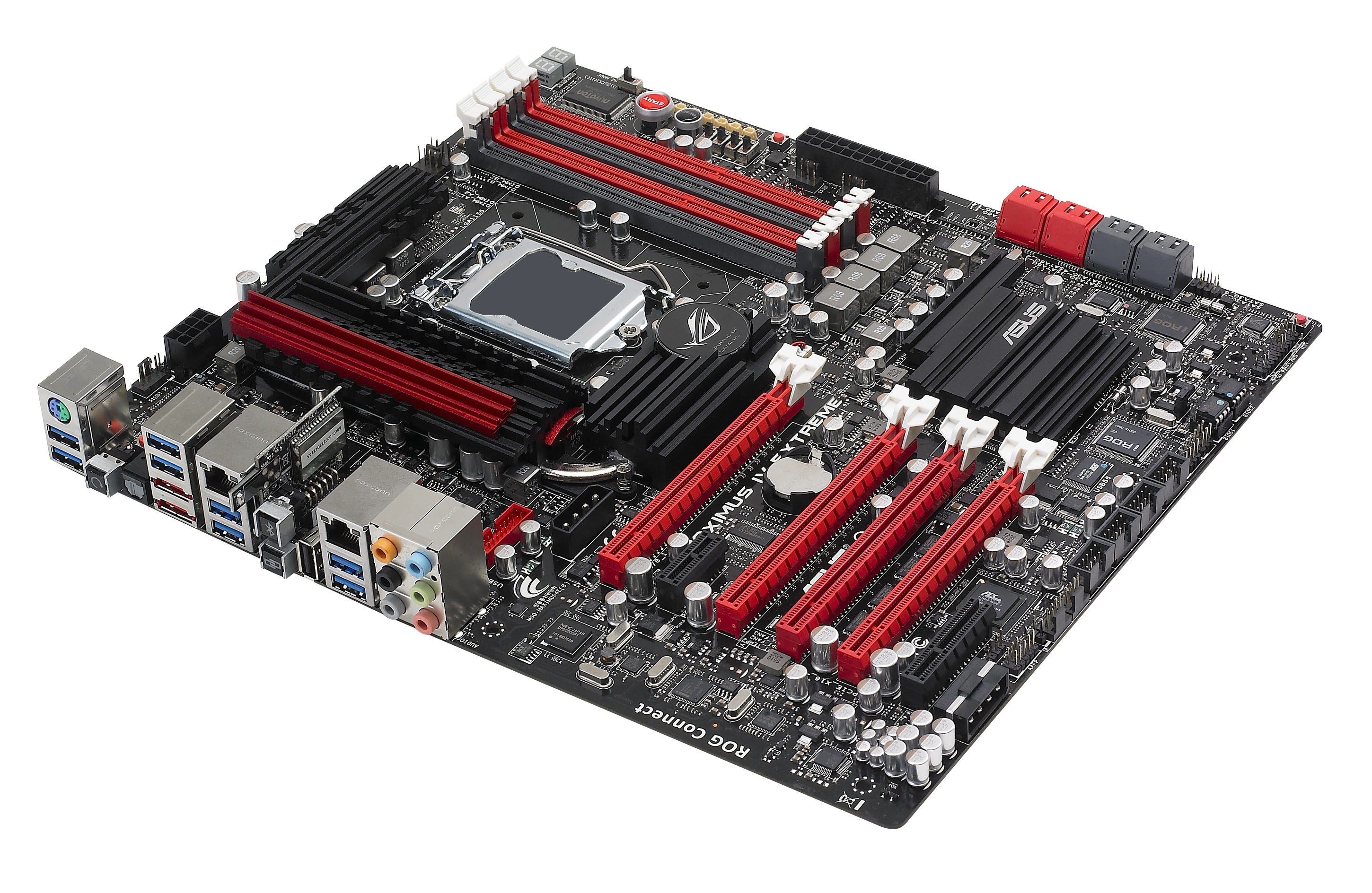
The red and black aside, ASUS are attempting to pushing the boat out for overclockers. Of immediate notice is beside the dual-channel DDR3 slots – alongside the power and reset buttons are a set of four switches, designed to enable and disable the PCIe slots as required. Beside these are a set of eight voltage readout points, allowing the monitoring of the various DRAM, NF200, PCH and the CPU voltages across the board. A switch is also present labelled ‘LN2_MODE’, which offers various questions as to what it does, but we suspect at least one of these features is to remove the overcurrent protection when the processor is under liquid nitrogen. One point of humorous mention is that there are three LEDs next to the DDR3 slots, one of them labelled ‘DDR_CRAZY’.
The Maximus IV operates a dual BIOS system, as directed by the two chips labelled BIOS1 and 2, and the BIOS switch in the bottom corner of the board. The dual-digit debugging LEDs, as we would expect, are present also.
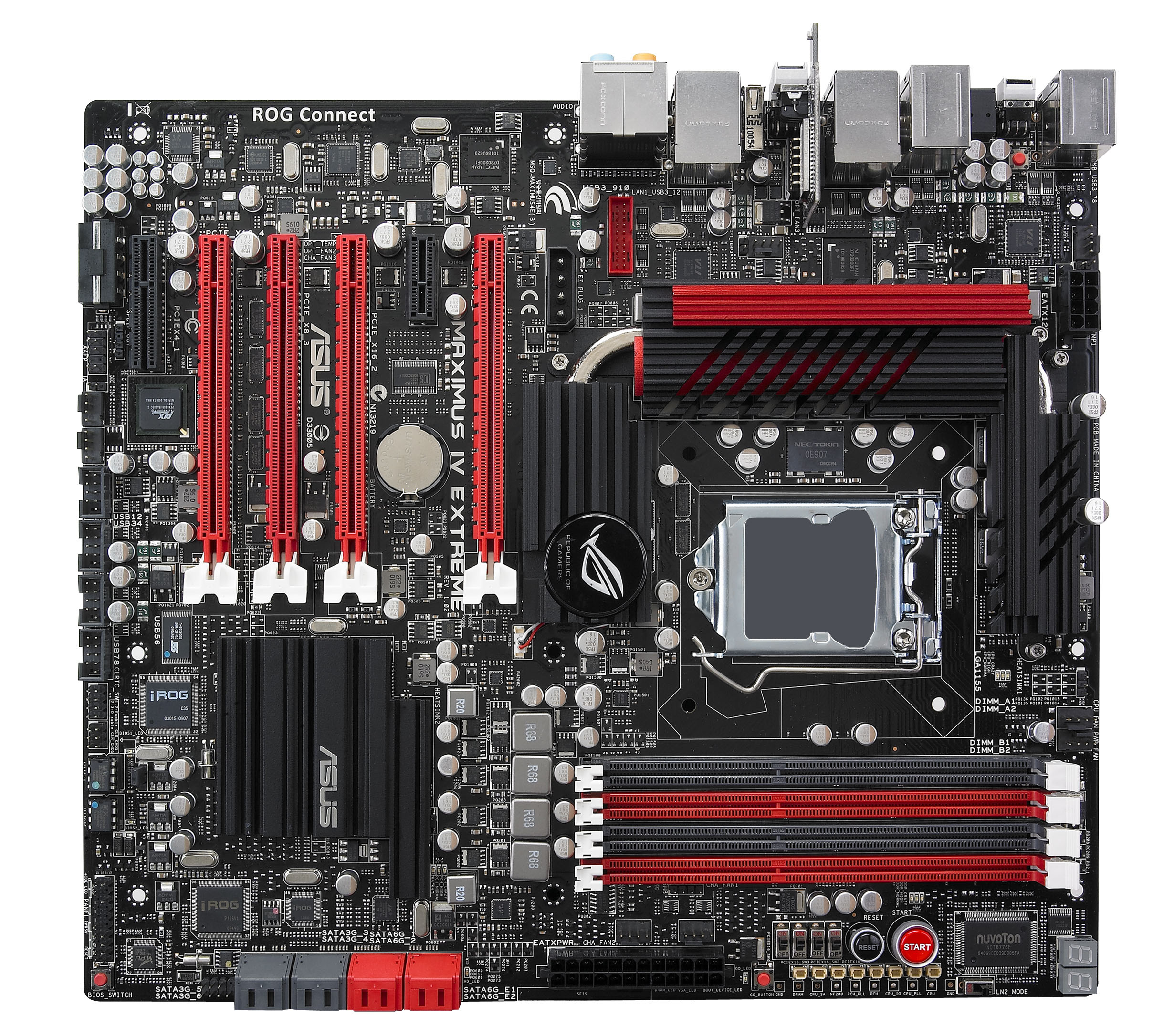
Surprisingly, only one 8-pin 12V connector is on the board, which is somewhat odd if the board has a liquid nitrogen mode and power needs to be pumped into the CPU. In terms of extra power for the PCIe slots, a 4-pin molex connector is provided where a PCIe x1 slot is found on the Pro and Deluxe boards. The board is obviously built for multiple graphics card use and overclocking, but as the P67 chipset is designed to only hold 16 PCIe lanes for graphics card usage – ASUS have added an NF200 chip to increase the amount of available lanes, presumably to 32 for an x16/x16 or x16/x8/x8 configuration. On previous motherboard generations, the NF200 chip accounts for a 1-2% loss in performance when the lanes are not fully utilised versus native support, as well as few more extra monies and power usage, thus all the GPU lanes need to be used to get the most out of the board – this is what the consumer is paying for, after all.
The back panel offers the usual myriad of USB 2.0 / 3.0, firewire, eSATA, 5.1 audio, PS/2 and dual Ethernet connectors, but the use of a mini-PCB perpendicular to the motherboard to supply the board with Bluetooth and what looks like a ROG connect switch is interesting. Also of note is an NEC/TOKIN Proadlizer film capacitor, similar to that used on some GPUs, directly next to the socket – presumably to provide more stable power to the socket.
Apart from the possible results this motherboard may or may not achieve, one thing is certain – it will be costing the consumer a pretty penny. No doubt we will have one in to test at some point, and we’ll keep our ears to the ground on other manufacturer’s flagship Sandy Bridge boards.


53 Comments
View All Comments
AnnihilatorX - Sunday, November 14, 2010 - link
"Surprisingly, only one 8-pin 12V connector is on the board, which is somewhat odd if the board has a liquid nitrogen mode and power needs to be pumped into the CPU."Just on the right hand side of the first PCIe X16 next to VRMs, there is also a 4-pin molex connector.
AnnihilatorX - Sunday, November 14, 2010 - link
Oh sorry I didn't see that you mentioned it. Are you sure the power just goes to PCIe only?IvanChess - Sunday, November 14, 2010 - link
I believe that 4-pin molex connector is a leftover from the AGP days and is actually meant to be plugged into the graphics card as an auxiliary power source. That's what it is on my board anyway.Kiji - Sunday, November 14, 2010 - link
Still no UEFI... :(Kiji - Sunday, November 14, 2010 - link
Scratch that. Seems that the entire P67 lineup from Asus comes with EFI (http://www.overclock3d.net/reviews/cpu_mainboard/a... Can someone tell me the difference between UEFI and EFI or how do they relate to each other ? Maybe Anandtech can do an article about that, since it will be a trend in 2011 :PXZerg - Monday, November 15, 2010 - link
EFI - Apple's version. UEFI - rest of the industry going to follow - Universal.ViRGE - Monday, November 15, 2010 - link
Close but no cigar. The early Intel-developed versions of EFI are officially known as EFI, while the later EFI versions starting in 2005 developed by the Unified EFI Forum are UEFI. So both Apple and Asus would be using UEFI.B3an - Monday, November 15, 2010 - link
You're not right either... atleast i'm pretty sure you're not. Macs still use EFI.PC's will get UEFI, which is basically EFI 2.0.
I know for certain that the current 2010 macbooks and pro's use EFI 1.1.
AmineBouhafs - Sunday, November 14, 2010 - link
"And on the fifth day of x-mas my true love sent to me...an Asus Maximus IV Extreme!" :pThe_Lauging_Man - Sunday, November 14, 2010 - link
Besides the extra 4-pin molex where the first PCIe x1 would be that was mentioned, I see a second right angle mounted 4-pin molex beneath the PCIe X4 slot. There is no mention in the article about this connector. Would both 4-pin molex be for powering the PCIe slots. I have a felling that this would not be the case, but can't say either way. I also like the plethora of 4-pin fan headers on the board.