The Neophyte's Custom Liquid Cooling Guide: How To, Why To, What To Expect
by Dustin Sklavos on September 30, 2013 12:01 AM ESTBefore you start assembling your loop, you'll really want a clear idea of how everything is going to route together. It will help to physically draw a diagram, even a hastily scribbled one, so you have some idea of how everything will connect. For the Corsair Carbide Air 540, I knew the cubby next to the power supply was where I wanted to put the reservoir and pump assembly. That meant that two lines were going to be routing back behind the motherboard: the line that flowed into the reservoir, and the line exiting the pump.
Below is the sequence I used for my loop, and it shouldn't be too hard to use it as a basic blueprint. This is undoubtedly going to create contention; I spent hours and hours reading posts on different watercooling forums before concluding that the simplest layout would be the best and easiest.
- Reservoir and pump assembly.
- Top radiator (240mm).
- Motherboard voltage circuitry.
- CPU waterblock (Apogee HD).
- First GeForce GTX 780 (KOMODO-NV).
- Second GeForce GTX 780 (KOMODO-NV).
- Front radiator (360mm).
- ...and back to the reservoir and pump assembly.
I spent a lot of time playing Tetris with the radiators, attaching and detaching the fans, trying to figure out exactly how everything would fit into the case and how everything would get connected. While the entire assembly probably could've taken only a couple of hours, my work on it went on over the course of three nights. Clearance issues reared their ugly heads a couple of times, necessitating the use of 45 degree and 90 degree adapters, sometimes even in sequence.
Compression in the foreground, worm clamp in the background.
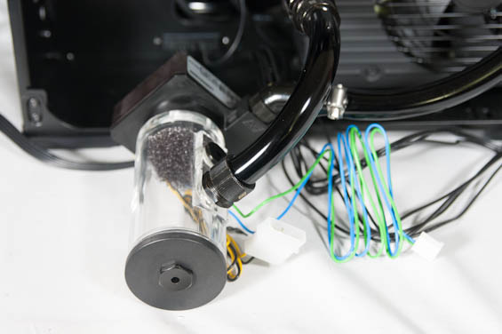
At this point I'm also going to admit the one thing I was most worried and ignorant about when I started this project specifically for those of you out there who are wondering about it, because I couldn't find any instructions in any of the tutorials I read for how to assemble a loop: how to actually connect the tubing to the individual blocks, radiators, reservoir, and pump.
The reservoir, waterblocks, radiators, and pump all have ports which fittings screw into (and screwing in those fittings is what you need the wrenches for). There are essentially two types of fittings I had to worry about: barbs and compressions. Barbs are the conical ports I mentioned earlier; the end of the tubing fits around the barb (typically pretty snugly and requiring a healthy amount of force), and then you use either a nylon clamp or a worm clamp. The nylon clamp snaps around the tubing and should be tightened with a pair of pliers, and is...adequate. The worm clamp needs to be loose and around the tubing before you affix it to the barb, and it's a royal pain to completely tighten because they all use flathead screws, but once it's on secure it's not going anywhere.
Compression fittings start with a barb you have to fit the tubing around, but before that there's a circular piece that goes around the tubing similar to the way you start with a worm clamp. The difference is that there's a set of threads below the barb, and the circular piece screws on to those. The lip in the circular piece squeezes the tubing, compressing it into place and sealing it. These can be extremely difficult to apply if you don't have a good grip and decent forearm strength, but they're tight, much easier to remove than worm clamps, and comparatively easy to connect.


106 Comments
View All Comments
hot120 - Monday, September 30, 2013 - link
Awesome article!blanarahul - Monday, September 30, 2013 - link
Hmm.. Can you try cooling those 780s alone? Overclocking the CPU seems pointless on Haswell.valkyrie743 - Monday, September 30, 2013 - link
overclocking haswell is not pointless. just is a pain (same with ivy bridge) cause intel decided to be cheap and not solder the IHS to the cpu. if you do a mild overclock its fine give or take how bad the tim on the cpu/ihs is. but if you plan on doing high overclocks and water cooling like this. you might as well de-lid the cpu and apply your own tim. temps on air (if done right) drop a good 15 to 20C under load. I've seen people hitting 90 C and go down to 70 or less underload. and thats on air.the reason why i have no upgraded from my sandy bridge 2600K. @4.5ghz right now at 1.28 volts and my max temp running intel burn test was 70C (air)
The Von Matrices - Monday, September 30, 2013 - link
Please read my post in response to NeatOman. The result is correct but the reasoning is incorrect.gandergray - Tuesday, October 1, 2013 - link
For information about removing the cpu lid or integrated heat spreader, see the work performed by Idontcare: http://forums.anandtech.com/showthread.php?t=22618... .iTzSnypah - Monday, September 30, 2013 - link
You are cooling way too much with only 600mm worth of radiators and your deltaT is obscene. Take out 1x GTX780 and retest if possible.NeatOman - Monday, September 30, 2013 - link
I think the thermal paste between the cpu and the lid are the limiting factor here, i believe that not only will 4770K do better with better thermal paste in between the lid and cpu on just air cooling alone but also might have a larger difference between the air and water cooling.And of course there is also a full delid which i think wont be much of a threat because with water cooling you don't need the motherboard to support a large heavy cooler.
NeatOman - Monday, September 30, 2013 - link
Sorry, i meant that you wont need to put a lot of pressure like if you where supporting a large air cooler with the motherboard.The Von Matrices - Monday, September 30, 2013 - link
The issue is not the composition of the thermal paste between the die and the lid; it is the thickness of the thermal paste between the die and the lid. It's widely reported that in Ivy Bridge and Haswell there is way too much of a gap between the die and the lid due to the thickness of the glue used to secure the lid to the package. You can solve this by removing the lid, using a razor blade to remove all the glue, then put on new TIM and place the lid back on the package. No matter what new TIM you use you will get drastically reduced temperatures.Either way, Haswell runs hot due to its FIVR, and there's nothing that can be done through beefier heatsinks, delidding, or changing thermal paste that will make it cooler than an equivalently modified Ivy Bridge.
dragosmp - Monday, September 30, 2013 - link
Still, it is incomplete. The thermal transfer formula is simply Rth=rho*L/S, more thermal resistance (Rth) more the temperature delta is high between the source and ambient: deltaT=Power*RthAsuming the power is constant, to decrease deltaT you need to decrease the thermal resistance, so:
*S is the die surface, can't change that
*L is the thickness of paste - you're right, it needs to be as thin as possible; put 2x too much and you have twice the deltaT
*rho - thermal resistivity (1/lambda) - it depends on the material; Intel does use cheap paste with a conductivity around 3; were they to use fluxless solder or at least some AS5 they'd decrease the thermal resitance by a factor of 2 easily, thus offsetting a thicker than needed layer of paste.
My 2 cents: for performance the paste must be removed and replaced with something better plus as you say remove the glue to reduce the thickness. Of course one should be careful not to chip the die, but these two things really help.