NVIDIA nForce 500: Biostar and MSI Aim for the Gold
by Gary Key on June 8, 2006 4:30 AM EST- Posted in
- Motherboards
Biostar TForce 590 SLI Deluxe: Board Layout
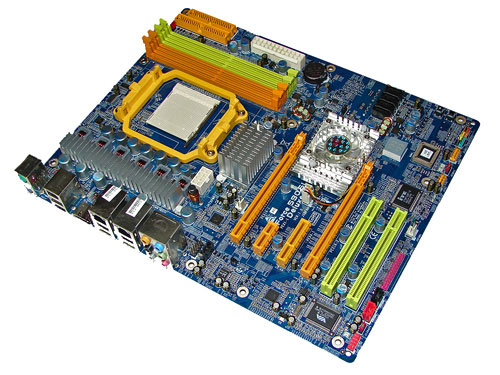
The Biostar is very well laid out with all major connections easily reached. The board did not have any obvious clearance issues and was easy to install in a mid-size ATX case. The board features an excellent 6-phase voltage regulator power design along with quality capacitors that yielded superb stability and overclocking results. The design boasts four fan headers with two being available for chassis fans.
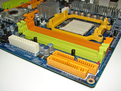
The DIMM module slots' color coordination is correct for dual channel setup based upon the premise of using the same colors for each memory bank. The memory modules are easy to install with a full size video card placed in the first PCI Express X16 slot. The single NVIDIA IDE port connector is located behind the floppy drive connector that is placed along the upper edge of the board. These ports did not present any connection issues in our mid-size ATX case and are correctly located for both IDE and Floppy devices. The white 24-pin ATX power connector is located along the edge of the board and below the memory modules.
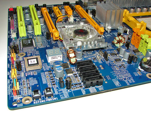
The four NVIDIA SATA ports are color coded black and are conveniently located below the NVIDIA MCP. The SATA ports feature the newer clamp and latch design. We found the positioning of the SATA ports to be excellent when installing our 7900 GTX SLI configuration. The NVIDIA MCP is actively cooled and based upon our thermal tests it is required. The fan was not overly loud and certainly could not be heard above the system fans.
Biostar provides on-board reset and power on buttons at the edge of the board, a feature that is greatly appreciated and very useful for boards not in a case. The chassis panel is located at the bottom edge of the board along with the two USB 2.0 headers. The BIOS chip and CP80 Debug LED are located between the USB headers and the MCP chipset. Last and actually least used is the clear CMOS jumper block that is a traditional jumper design located below the NVIDIA MCP. We did not utilize this jumper throughout our two weeks of testing this board but did notice it would be extremely difficult to reach in an SLI configuration.
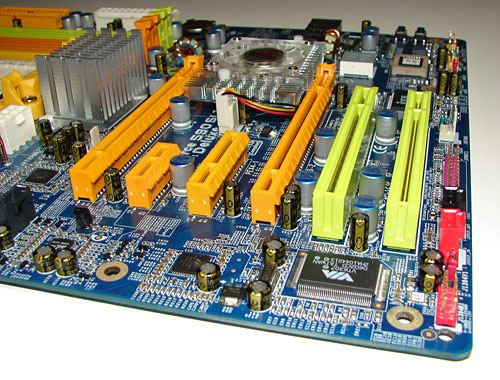
The Biostar comes with (2) PCI Express X16 connectors, (1) PCI Express X1 connector, (1) PCI Express X4 connector, and (2) PCI 2.3 connectors. This layout offers a good balance of expansion slots for an enthusiast board while providing very good clearance space for card utilization.
The first PCI Express X16 connector is located to the far left of the slot areas. The PCI Express X1 connector is located next, followed by the PCI Express X4 connector, the second PCE Express X16 connector, and then the (2) PCI slots. The two physical X16 connectors available on the board both operate in X16 PCI-E mode in SLI mode.
We did not have any issues installing our EVGA 7900 GTX 512MB video cards in the first or second X16 PCI Express slots. A dual slot card located in the first X16 connector will physically render the X1 PCI Express slot useless and a dual slot card in the second X16 connector will physically render the first PCI 2.3 slot useless. There were no issues utilizing either slot with video cards containing single slot cooling systems.
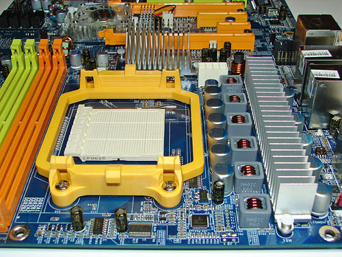
Returning to the CPU socket area, we find an ample amount of room for alternative cooling solutions. We utilized a Zalman CNPS9500 AM2 cooler without issue and believe similar cooling solutions would fit in this area. However, until we receive additional AM2 cooling solutions for verification it would be wise stay within the dimensions of the Zalman cooler.
The NVIDIA SPP is passively cooled with a medium sized heatsink unit that did not interfere with any installed peripherals. In fact this unit kept the chipset cool enough that additional chipset voltage was not a factor in our overclocking tests.
Biostar places the eight-pin 12v auxiliary power connector at the top of the CPU socket area and out of the way of our cooling solutions. However, this connector is located in a position that can hamper airflow with cabling that crosses directly over the CPU heatsink/fan.
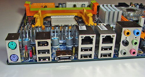
The rear panel contains the standard PS/2 mouse and keyboard ports, IEEE-1394a port, two LAN ports, and 6 USB ports. Each LAN (RJ-45) port has two LED indicators representing Activity and Speed of the connection. The audio panel consists of 6 ports that can be configured for 2, 4, 6, and 8-channel audio connections. The panel also consists of two non-powered external SATA 3Gb/s ports although our sample only contained a single port. Biostar has dropped the serial and parallel ports in favor of the additional USB ports.
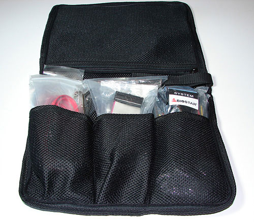
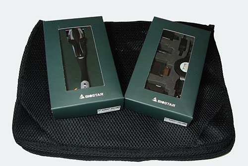
One of the more useful options we have seen in a motherboard kit is this nylon carrying bag for accessories. Speaking of accessories, Biostar also includes a headset and universal USB adapter kit along with the usual cables and power plugs.
 |
| Click to enlarge |
The Biostar is very well laid out with all major connections easily reached. The board did not have any obvious clearance issues and was easy to install in a mid-size ATX case. The board features an excellent 6-phase voltage regulator power design along with quality capacitors that yielded superb stability and overclocking results. The design boasts four fan headers with two being available for chassis fans.

The DIMM module slots' color coordination is correct for dual channel setup based upon the premise of using the same colors for each memory bank. The memory modules are easy to install with a full size video card placed in the first PCI Express X16 slot. The single NVIDIA IDE port connector is located behind the floppy drive connector that is placed along the upper edge of the board. These ports did not present any connection issues in our mid-size ATX case and are correctly located for both IDE and Floppy devices. The white 24-pin ATX power connector is located along the edge of the board and below the memory modules.

The four NVIDIA SATA ports are color coded black and are conveniently located below the NVIDIA MCP. The SATA ports feature the newer clamp and latch design. We found the positioning of the SATA ports to be excellent when installing our 7900 GTX SLI configuration. The NVIDIA MCP is actively cooled and based upon our thermal tests it is required. The fan was not overly loud and certainly could not be heard above the system fans.
Biostar provides on-board reset and power on buttons at the edge of the board, a feature that is greatly appreciated and very useful for boards not in a case. The chassis panel is located at the bottom edge of the board along with the two USB 2.0 headers. The BIOS chip and CP80 Debug LED are located between the USB headers and the MCP chipset. Last and actually least used is the clear CMOS jumper block that is a traditional jumper design located below the NVIDIA MCP. We did not utilize this jumper throughout our two weeks of testing this board but did notice it would be extremely difficult to reach in an SLI configuration.

The Biostar comes with (2) PCI Express X16 connectors, (1) PCI Express X1 connector, (1) PCI Express X4 connector, and (2) PCI 2.3 connectors. This layout offers a good balance of expansion slots for an enthusiast board while providing very good clearance space for card utilization.
The first PCI Express X16 connector is located to the far left of the slot areas. The PCI Express X1 connector is located next, followed by the PCI Express X4 connector, the second PCE Express X16 connector, and then the (2) PCI slots. The two physical X16 connectors available on the board both operate in X16 PCI-E mode in SLI mode.
We did not have any issues installing our EVGA 7900 GTX 512MB video cards in the first or second X16 PCI Express slots. A dual slot card located in the first X16 connector will physically render the X1 PCI Express slot useless and a dual slot card in the second X16 connector will physically render the first PCI 2.3 slot useless. There were no issues utilizing either slot with video cards containing single slot cooling systems.
 |
| Click to enlarge |
Returning to the CPU socket area, we find an ample amount of room for alternative cooling solutions. We utilized a Zalman CNPS9500 AM2 cooler without issue and believe similar cooling solutions would fit in this area. However, until we receive additional AM2 cooling solutions for verification it would be wise stay within the dimensions of the Zalman cooler.
The NVIDIA SPP is passively cooled with a medium sized heatsink unit that did not interfere with any installed peripherals. In fact this unit kept the chipset cool enough that additional chipset voltage was not a factor in our overclocking tests.
Biostar places the eight-pin 12v auxiliary power connector at the top of the CPU socket area and out of the way of our cooling solutions. However, this connector is located in a position that can hamper airflow with cabling that crosses directly over the CPU heatsink/fan.

The rear panel contains the standard PS/2 mouse and keyboard ports, IEEE-1394a port, two LAN ports, and 6 USB ports. Each LAN (RJ-45) port has two LED indicators representing Activity and Speed of the connection. The audio panel consists of 6 ports that can be configured for 2, 4, 6, and 8-channel audio connections. The panel also consists of two non-powered external SATA 3Gb/s ports although our sample only contained a single port. Biostar has dropped the serial and parallel ports in favor of the additional USB ports.


One of the more useful options we have seen in a motherboard kit is this nylon carrying bag for accessories. Speaking of accessories, Biostar also includes a headset and universal USB adapter kit along with the usual cables and power plugs.


17 Comments
View All Comments
dougcook - Friday, September 8, 2006 - link
I bought one of the MSI 570 boards (after reading this review). Everything seemed ok (some things seemed a bit cheap, but nothing really unusual). I got it all installed and running...For one day.
While burning a few CDs, the Northbridge overheated and the machine turned itself off. This happened 2 more times, and then the machine failed to boot at all (even after giving it time to cool off). I wasn't overclocking, and the box had decent ventilation.
This may not happen for everybody, but looking on NewEgg, it seems that this has happened to many other people. The MSI northbridge does not have an adequate heatsink and is likely to burn up. Save the time and get something better. I got the equivalent ABit 570 motherboard, and I've been very happy so far. I hear good things about the ASUS 570 as well.
MacGuffin - Wednesday, June 21, 2006 - link
I don't mean to be a whiny biyatch but where's the follow-up article? Are you guys playing around with Conroe motherboards and ES chips again?;-)JakeBlade - Friday, June 9, 2006 - link
Northbridge fans blow. No pun intended.Visual - Friday, June 9, 2006 - link
in the comparison table on page 2, you have incorectly listed a firewire, 6 usb ports and 2 esata ports for the MSI. it doesn't have those, just 4 usbs. it does have a COM and LPT ports that you need to list though.Gary Key - Friday, June 9, 2006 - link
The right table was inserted this time, thanks!!!! :)A554SS1N - Friday, June 9, 2006 - link
I'm interested in the MSI K9N 550 chipset, but noticed this 570 SLi chipset has the same sized passive cooler; could you tell me what the temperatures for the chipet on load are? (Sometimes SpeedFan might be needed to detect them on some boards?).Gary Key - Friday, June 9, 2006 - link
I will see if we can get an accurate internal chipset temperature for you. The heatsink itself was at 56c under load when measured with a infrared device.A554SS1N - Thursday, June 15, 2006 - link
Thanks, I could get an idea that it may be upto 70C internal from that external heatsink reading.R3MF - Thursday, June 8, 2006 - link
sorry, not buying.give me the 8x/16x SLI split, as well as 8x slot, two 1x slots, and a couple of PCI slots that i can ignore.
then i'll buy.
segagenesis - Thursday, June 8, 2006 - link
... is its AMD. After reading about Conroe I would hope nVidia does this for the Intel camp now that I'd rather buy one of those than AM2.