DFI UT P35-T2R: Tweakers Rejoice!
by Rajinder Gill on October 18, 2007 2:00 PM EST- Posted in
- Motherboards
Board Features
Our typical expectations were to see the standard orange or yellow LANParty color scheme, change is in the air and lime green is the flavor of the month. No matter the color scheme, the general layout of this board is nearly flawless.
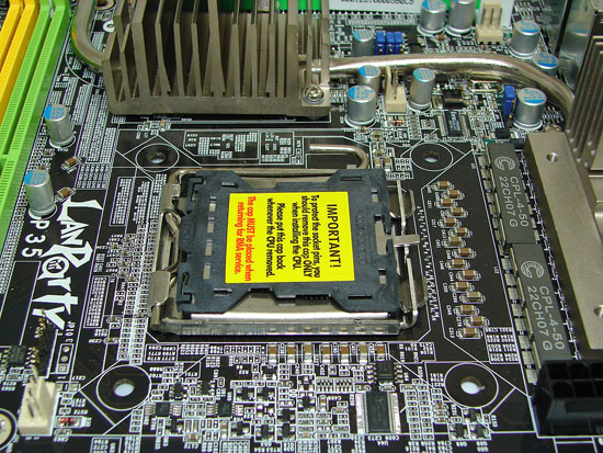
A clean CPU socket area ensures compatibility with large air-coolers. We do recommend that users consider having enough space for an additional fan to provide airflow over the PWM and Northbridge heatsink, if they intend to use more than 1.6V on the Northbridge. The 8-pin power connector sits at the top left corner of the board, close to the PWM circuitry, with enough room to allow the use of bulkier connectors without any interference from surrounding components.
A more noteworthy subject is the 8-phase Digital PWM circuit, using the Volterra VT1115MF buck controller and associated fast-switching, high-bandwidth "Digital" MOSFETs. This solution has received mixed responses from overclockers, some feeling that Digital PWM does not have sufficient durability for an extreme overclocking motherboard. The current 8-phase design has managed to run overclocked quad-core CPUs completely Prime load stable at speeds of up to 4GHz. However, the jury is still out as to the effectiveness of the current Digital PWM design when quad-core CPUs are super-cooled. In the past, VCore settings over 1.6V and CPU speeds over 4GHz have not fared too well on lesser 6-phase implementations of DPWM, especially in high CPU load benchmarks.
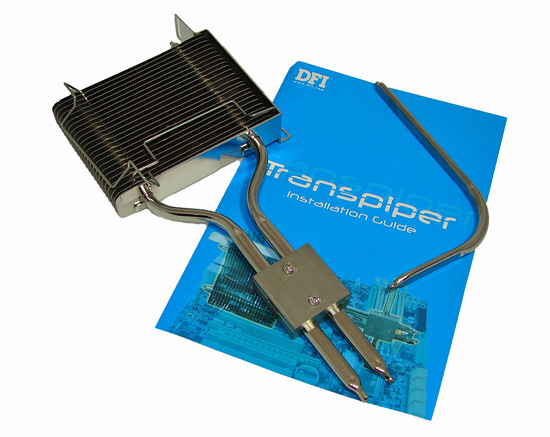
DFI utilizes a heat pipe system that connects the PWM, P35, and ICH9R together to provide a cooling solution that works quite well, until you really push the board. At that point, additional cooling from active air or water solutions is required to properly cool these critical components. DFI engineered an extension joint (Transpiper) that attaches to the ICH9R heatsink to help carry heat within this system out of the chassis. There are numerous mounting configurations, with the most logical being to connect the highest heat producing area (the PWM heatsink) and have the Transpiper assembly exiting the PC case, so that heat is removed from the case, in theory reducing all internal component temperatures.
This system typically worked well with an air-cooling setup on the CPU and pushing the board to its limits on air. However, we did not notice any benefits during heavy overclocking sessions with water or cascade cooling. In fact, the hot air exiting the test case from our OCZ 1000W or 1200W power supplies seemed to have a reverse effect during extended overclocking sessions with the Transpiper located in front of the PSU fan as recommended by DFI. As such, DFI offers a version of this board without the Transpiper option for these users, or ones who want to save about $20.
That's not all; there is also a heat transfer plate that can connect from the CPU IHS to the PWM heatsink, sandwiched between the IHS and user CPU cooling solution. Our own thoughts are that users are best advised not to use this plate, as the temperature of both the PWM and CPU seem to suffer as a result. A closer look at the PWM heatsink mounting holes for this transfer plate shows that the width between the two holes is only a quarter of an inch offset from the mounting dimensions of the already available MIPS DFI 680i LT MOSFET waterblock (the key phrase here is "already available"). Had the holes on the PWM heatsink aligned with the MIPS 680i LT block without requiring a redesign ,or the removal of DFI's own PWM heatsink for functionality, current owners of the block and perspective water-cooling users could have been saved some time and perhaps money.
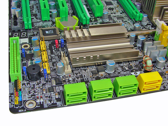
DFI once again adhered to their typically overclocking friendly layout, easily accessible CMOS battery, onboard power and reset switches featuring EZ CMOS clear, and of course the LED POST Code display. The floppy drive connector sits at the lower edge of the board to the right of the POST Code display. The six Intel ICH9R SATA ports are located at the lower right edge of the board, facing to the right making connector insertion a little awkward at times once the board is mounted in a case. There are also two JMicron JMB363 SATA ports situated above the Intel SATA ports.
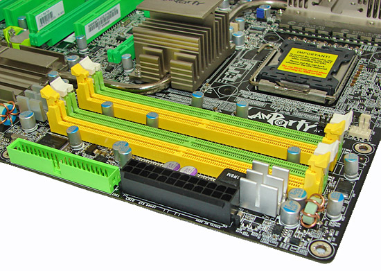
The memory slot connectors are situated almost in line with the primary PCI Express connector; large graphics cards such as the 8800 GTX may have to be removed when swapping out memory modules. The 24-pin ATX connector is placed to the right of the slots and does not hinder the use of the IDE connector below it. There are six onboard fan headers, all logically placed in high heat production areas, with both BIOS and OS Smart Guardian fan control options.
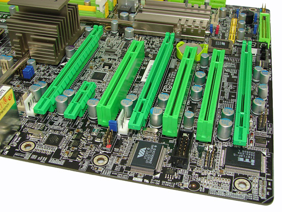
The expansion slot layout is comprised of three PCI Express x16 slots (one x16, one x4, and one x1 slot), one PCI Express x1 slot, and three PCI slots. The supplied Bernstein Audio module features the Realtek ALC885 8-channel High Definition Audio CODEC and has its dedicated connector placed between the PCI slots, rendering one of the PCI slots inactive if the module is used. There are three onboard USB connectors for an additional six USB ports, a connector for an external COM port, one IrDA connector, one CIR connector, and a connector for the second IEEE-1394 port.
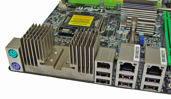
The rear I/O options include six USB ports, an IEEE-1394 port, two Gigabit LAN ports with teaming options, and finally the standard PS/2 keyboard and mouse ports.
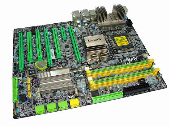 |
Our typical expectations were to see the standard orange or yellow LANParty color scheme, change is in the air and lime green is the flavor of the month. No matter the color scheme, the general layout of this board is nearly flawless.

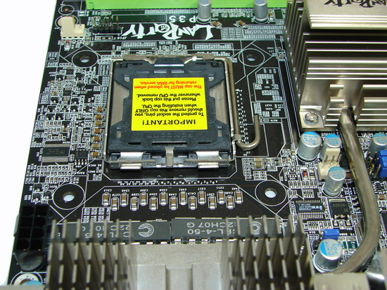 |
A clean CPU socket area ensures compatibility with large air-coolers. We do recommend that users consider having enough space for an additional fan to provide airflow over the PWM and Northbridge heatsink, if they intend to use more than 1.6V on the Northbridge. The 8-pin power connector sits at the top left corner of the board, close to the PWM circuitry, with enough room to allow the use of bulkier connectors without any interference from surrounding components.
A more noteworthy subject is the 8-phase Digital PWM circuit, using the Volterra VT1115MF buck controller and associated fast-switching, high-bandwidth "Digital" MOSFETs. This solution has received mixed responses from overclockers, some feeling that Digital PWM does not have sufficient durability for an extreme overclocking motherboard. The current 8-phase design has managed to run overclocked quad-core CPUs completely Prime load stable at speeds of up to 4GHz. However, the jury is still out as to the effectiveness of the current Digital PWM design when quad-core CPUs are super-cooled. In the past, VCore settings over 1.6V and CPU speeds over 4GHz have not fared too well on lesser 6-phase implementations of DPWM, especially in high CPU load benchmarks.

DFI utilizes a heat pipe system that connects the PWM, P35, and ICH9R together to provide a cooling solution that works quite well, until you really push the board. At that point, additional cooling from active air or water solutions is required to properly cool these critical components. DFI engineered an extension joint (Transpiper) that attaches to the ICH9R heatsink to help carry heat within this system out of the chassis. There are numerous mounting configurations, with the most logical being to connect the highest heat producing area (the PWM heatsink) and have the Transpiper assembly exiting the PC case, so that heat is removed from the case, in theory reducing all internal component temperatures.
This system typically worked well with an air-cooling setup on the CPU and pushing the board to its limits on air. However, we did not notice any benefits during heavy overclocking sessions with water or cascade cooling. In fact, the hot air exiting the test case from our OCZ 1000W or 1200W power supplies seemed to have a reverse effect during extended overclocking sessions with the Transpiper located in front of the PSU fan as recommended by DFI. As such, DFI offers a version of this board without the Transpiper option for these users, or ones who want to save about $20.
That's not all; there is also a heat transfer plate that can connect from the CPU IHS to the PWM heatsink, sandwiched between the IHS and user CPU cooling solution. Our own thoughts are that users are best advised not to use this plate, as the temperature of both the PWM and CPU seem to suffer as a result. A closer look at the PWM heatsink mounting holes for this transfer plate shows that the width between the two holes is only a quarter of an inch offset from the mounting dimensions of the already available MIPS DFI 680i LT MOSFET waterblock (the key phrase here is "already available"). Had the holes on the PWM heatsink aligned with the MIPS 680i LT block without requiring a redesign ,or the removal of DFI's own PWM heatsink for functionality, current owners of the block and perspective water-cooling users could have been saved some time and perhaps money.


DFI once again adhered to their typically overclocking friendly layout, easily accessible CMOS battery, onboard power and reset switches featuring EZ CMOS clear, and of course the LED POST Code display. The floppy drive connector sits at the lower edge of the board to the right of the POST Code display. The six Intel ICH9R SATA ports are located at the lower right edge of the board, facing to the right making connector insertion a little awkward at times once the board is mounted in a case. There are also two JMicron JMB363 SATA ports situated above the Intel SATA ports.
The memory slot connectors are situated almost in line with the primary PCI Express connector; large graphics cards such as the 8800 GTX may have to be removed when swapping out memory modules. The 24-pin ATX connector is placed to the right of the slots and does not hinder the use of the IDE connector below it. There are six onboard fan headers, all logically placed in high heat production areas, with both BIOS and OS Smart Guardian fan control options.

The expansion slot layout is comprised of three PCI Express x16 slots (one x16, one x4, and one x1 slot), one PCI Express x1 slot, and three PCI slots. The supplied Bernstein Audio module features the Realtek ALC885 8-channel High Definition Audio CODEC and has its dedicated connector placed between the PCI slots, rendering one of the PCI slots inactive if the module is used. There are three onboard USB connectors for an additional six USB ports, a connector for an external COM port, one IrDA connector, one CIR connector, and a connector for the second IEEE-1394 port.

The rear I/O options include six USB ports, an IEEE-1394 port, two Gigabit LAN ports with teaming options, and finally the standard PS/2 keyboard and mouse ports.


30 Comments
View All Comments
Rocket321 - Tuesday, October 23, 2007 - link
I would like to see the overclocking results put into a graph or chart of some kind.I guess tweakers might like the screenshots as "proof" that the overclock ran, but personally I trust you and would rather just have one place to look rather than clicking to enlarge multiple screenshots sequentially.
It was a great review though, I look forward to the future tweaker guides & reviews.
Raja Gill - Wednesday, October 24, 2007 - link
There will be a more typical Anandtech look to future articles, with the DFI board revisited for a round up on a suite of benchmarks, this will be used to cross compare with other boards, clocked to equivalent with board maximums in the range and voltage. In terms of the screenshots, it is nice to have 1 persons trust, but there are many we have to please and not everyone is always as convinced..thanks for the suggestions..
Next up is the Asus Maximus Formula..
regards
Raja
Jodiuh - Thursday, October 25, 2007 - link
Specifically Windvd conversions from divx/xvid to DVD would be wonderful as I've found this app benefits from a solid OC.beoba - Friday, October 19, 2007 - link
It'd be great if this came with a glossary."Strap"?
retrospooty - Saturday, October 20, 2007 - link
strap is a term used for memory clocking. for example, at 266mhz bus, memory can be "strapped" to one of the following.266x(stap2)=533 or DDR 1066
266x(strap1.5)=400 or DDR 800
266x(strap1.25)=333 or DDR 666
If you are running at stock 266 there is no way to have DDR 950 because it has to be strapped to one of the above settings.
I use the 1/1 strap so my bus speed is 500x(strap1)=500 or DDR 1000, in most cases 1/1 is the most efficient, if you can utilize it with your particular hardware, do it.
Avalon - Thursday, October 18, 2007 - link
Unfortunately, DFI's asking price of admission continues to rise for each new board they release. I was mildly annoyed when they started selling boards for $200+ that had little to no tangible benefit over $100-$150 boards, but now they're at the $300 mark? No thanks.This board is for someone who likes to spend his time tweaking and not actually using his computer.
retrospooty - Saturday, October 20, 2007 - link
"This board is for someone who likes to spend his time tweaking and not actually using his computer."The article title is called "Tweakers Rejoice" after all. The idea is not to tweak forever . I did spend alot of time over the first few weeks, but now that its tweaked, I just use it as is.
Avalon - Sunday, October 21, 2007 - link
Yes, I am quite capable of reading the article title. My whole point is that you are working for diminishing returns that I feel could be better spent using your system. If you're doing it to set a record, fantastic. I support that.retrospooty - Sunday, October 21, 2007 - link
Understood... This is obviously not the motherboard for you. I personally love the BIOS options and CMOS reloaded functionality. That alone makes the extra cost well worth it to me. Asus BIOS just sucks, and I have had too many quality problems with them in the past, and Gigabyte just underperforms. I like to know I will not be held back by my motherboard for the next couple of CPU's I buy (will likely get a dual core Penryn on release for under $200, then a high end quad core Penryn a year or so later when it is under $200).I do see your point, but in spite of this article's stock speed comparison (totally pointless for a OC geared mobo), and similar results with one particular CPU, that looks as if it has an FSB limit equal on all 3 boards (meaning the CPU is holding it back) This board overclocks and performs better than any ASUS, or Gigabyte, or any other board out there. If AT tested the max FSB limits on a dozen or so CPU's, or if they had a "golden sample" that had a high FSB limit, you would see the difference. Also if they had time to test many diff RAM stocks and to tweak the memory settings you would also see the difference. Its a good article, but no reviewer has time to really dig into this mobo and all it has to offer. I do feel the article did a good job at explaining that.
JNo - Sunday, October 21, 2007 - link
"I like to know I will not be held back by my motherboard for the next couple of CPU's I buy"I don't know much about overclocking and I hold your views valid Retrospooty but surely this is still a lot of money that will still be needed to replaced in the short/medium-term if a) you want to start using DDR3 once prices come down b) if GPUs come out that take advantage of PCI-E 2 standard (as used on X38). So all that money is only paying for great OC'ing potential for *now* only... no?