Silver Power Blue Lightning 600W
by Christoph Katzer on August 27, 2007 6:00 AM EST- Posted in
- Cases/Cooling/PSUs
The Internals
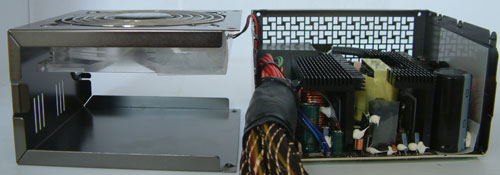
Credit where credit is due: Silver Power has managed to create the most difficult power supply casing to crack that we have encountered so far. We have no idea who came up with the design or why they would want it, as logically it must be just as difficult to seal up as it was for us to open. We can only feel sorry for the poor soul sitting at the end of the assembly line tasked with the job of closing up the power supplies. The two sides are designed in a "U" shape and slide into each other. The fan and various cables do an excellent job of getting in the way, particularly the cable harness that leads to all of the connectors. Very few people actually try to open up their power supplies anyway, so unless there's some trick to assembly that we can't figure out, the net result is that none of this can be good for productivity and appears to serve no real purpose.
The construction of the casing makes it very difficult to get a clear view of the various components, as something else always seems to be getting in the way. We did manage to get the PCB out of the case in order to take better pictures after testing but the above image gives you an idea of how everything is arranged.
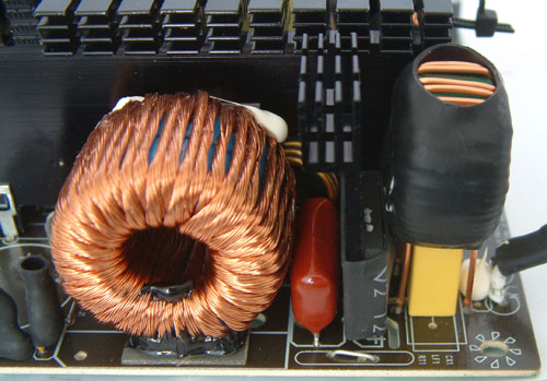
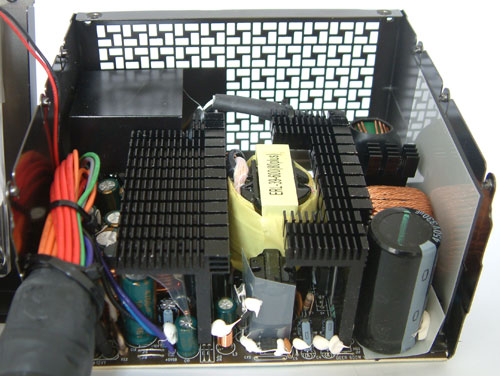
Most of the filtering is done directly behind the AC jack. A couple of capacitors are placed on the right side just before the rectifying bridge. The bridge itself is attached to its own small heatsink, as it can become quite warm during use.
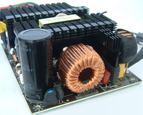
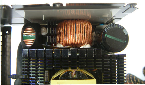
Next to the bridge we find the standard PFC stage and the main capacitor. The main capacitor is made by Teapo and labeled as 450V and 330µF at just 85°C.
Credit where credit is due: Silver Power has managed to create the most difficult power supply casing to crack that we have encountered so far. We have no idea who came up with the design or why they would want it, as logically it must be just as difficult to seal up as it was for us to open. We can only feel sorry for the poor soul sitting at the end of the assembly line tasked with the job of closing up the power supplies. The two sides are designed in a "U" shape and slide into each other. The fan and various cables do an excellent job of getting in the way, particularly the cable harness that leads to all of the connectors. Very few people actually try to open up their power supplies anyway, so unless there's some trick to assembly that we can't figure out, the net result is that none of this can be good for productivity and appears to serve no real purpose.
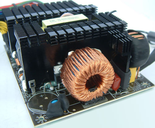
The construction of the casing makes it very difficult to get a clear view of the various components, as something else always seems to be getting in the way. We did manage to get the PCB out of the case in order to take better pictures after testing but the above image gives you an idea of how everything is arranged.
Most of the filtering is done directly behind the AC jack. A couple of capacitors are placed on the right side just before the rectifying bridge. The bridge itself is attached to its own small heatsink, as it can become quite warm during use.
Next to the bridge we find the standard PFC stage and the main capacitor. The main capacitor is made by Teapo and labeled as 450V and 330µF at just 85°C.


33 Comments
View All Comments
Per Hansson - Monday, August 27, 2007 - link
If you take a DMM and measure the power drop on the actual molex connectors, and not take the results directly from the Chroma how does it look then?I suspect you have an exponential increase in resistance which causes the Chroma to display incorrect voltage values... (Because of the cable length from the PSU's connectors and up to your load, including interface boards)
Sincerely - Per Hansson
MrOblivious - Monday, August 27, 2007 - link
Well that and if this really is a Solytech (Deer) it could just be a flaming hunk of crap.Per Hansson - Monday, August 27, 2007 - link
Yea, but the voltage resistance issue is something that has been the same for all PSU reviews here at AnandWhen you have this problem with all PSU's you need to realize there is something wrong with your testing equipment, sorry for being so blunt... (Especially since none of the other 2 big sites report the same)
And yes, some scope readings for this DEER PSU sure would have been interesting (just to make sure to beat the dead horse a bit more)
Christoph Katzer - Tuesday, August 28, 2007 - link
Strange though that the Zippy G1 has nearly the whole time close to to 12.0v. I have seen reports from the companies and they look similar (also the high efficiency) and thus I don't think the resistance will be a big issue.MrOblivious - Tuesday, August 28, 2007 - link
Are they using a Chroma as well for those test reports? Or are they reading directly at the connector without another interface like the spec calls for?Christoph Katzer - Tuesday, August 28, 2007 - link
"Every" company in Taiwan uses Chroma for their own evaluations.Per Hansson - Tuesday, August 28, 2007 - link
Christoph Katzer; The issue is of course not that you are using the Croma, it's a great unit; however, the way you use it will most likely result in incorrect voltage readingsDue to the fact that the resistance in the cables loading the unit will most likely result in a exponential increase in resistance, therefore the results shown by the Chroma will be incorrect, and more incorrect as the load increases and the resistance exponentially increases...
Just putting a multimeter on an unloaded Molex connector, or, directly on the molex connector you are loading (and not further down where the chroma reads the voltage) would quickly prove or disprove my theory
mindless1 - Thursday, August 30, 2007 - link
You are correct, that a high enough current on too low a wire gauge does cause significant voltage drop, I have observed it many times myself particularly with some of the poorer PSU using 12V connectors with less than 18 ga. wires.However, similarly we can't just take the reading from an unused molex connector instead, as a PSU is spec'd to provide it's voltages at the load through the existing wiring harness. It is not necessary to try to evenly distribute that load across all the wire pairs in that harness as that is a practically impossible scenario for implementation running a system, so a bit of a derating factor is needed to appoximate the typical expected loads. IMO, a good start would be loading each supply wire at about 6A (not counting ground returns) up until the rating per rail is met, leaving some supply wires per rail unused when (sum of rail wires * 6A) > rated current per rail. Obviously some connectors and leads are more robust and necessary than others, for example a floppy connector should just be ignored while the 2 x n 12V CPU connector should always be used.
mindless1 - Thursday, August 30, 2007 - link
I meant, high enough current on too high, too small a wire gauge.JarredWalton - Tuesday, August 28, 2007 - link
But wouldn't regular PC components drawing power from a PSU result in the same sort of increase in resistance? (Note: I'm not at all an electrician, so I could be wrong. Just asking a question.)